Input Filter
The input filter is used for both channels to reduce noise and to make it possible to measure the voltage.
Common Mode voltage setting
With the resistor of 1 MΩ one input signal is connected to the GND of the board to measure the resulting voltage of the thermocouple.
RFI Filter
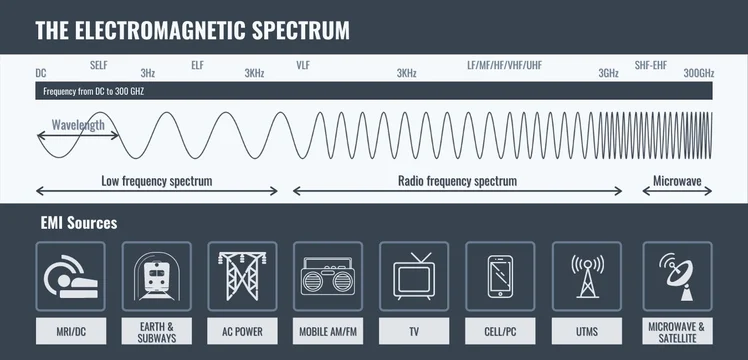
In the world, every cable is directly a small antenna, which reacts with the wide spectrum of electromagnetic waves and disturb the temperature signal.
To remove this noise, a passive RC low pass filter is used between the input lines and ground as well as between the two input lines. The cutoff frequency is calculated as follows:
With the current values for the resistors of 100 Ω and the capacitors to GND of 100nF, the cutoff frequency results in $$f_{ccm} = 15.9kHz$$
The cutoff frequency between the two input lines results the capacitor of 100μF
$$f_{cDiff} = 758Hz$$
Input Switch
With the mechanical input switch, the user decide which input direction is used. The current state of the switch will be forwarded to the micro controller and as well as to the LED module. Decide between the digital option and analog option.
LED module
In that module the current state is displayed to the user with two different colors.
Digital: Blue
Analog: Orange