Ex-21: HAL Interrupt Handling
Interrupts allow the MCU to react fast to asynchronous events.
The interrupts with the HAL driver are handled by the library.
To connect them with the user code, HAL offers handler functions which can be used for the implementation.
These handler functions are used in this exercise to implement the measurement of the active time of the center switch button.
The measured time will be visualized with a LED which lights up for the corresponding duration.
Objectives
HAL Interrupt Handler
EXTI Interrupt
Timer Interrupt
GPIO output duration control
Outcomes
Understanding the structure of the hal interrupt handlers
Enabling Interrupts in CubeMX
Implementing full Interrupt Control
Description
The goal of this exercise is to measure the time between the rising and falling edge on the center switch button.
During pressing the button, the blue LED lights up.
To display the measured time, the green LED is enabled as long as the measured time and starts immediately after releasing the button.
A new measurement can only be started again once the visualization process has been completed.
To solve this exercise, the GPIO and Systick interrupt from the HAL driver will be used.
Interrupts increase the reaction speed to events and are often used in embedded systems for time critical applications.
To use them with the HAL library, HAL offers an abstraction of the interrupt handlers from the vector table.
All enabled interrupts are collected in the file stm32f4xx_it.c with their interrupt service routine (ISR) from the vector table.
For most peripheral interrupts, HAL opens its own abstracted interrupt handler function within the ISR functions.
This interrupt handler then clears the interrupt and calls a specific callback function.
This callback function is defined as __weak and can be overwritten by the user to allow a specific implementation.
Hint
Remember to the abstraction of interrupts from the last semester.
HAL handles the interrupt interfaces in another way than the vector table. HAL collects the interrupts from the same peripheral type (i.e. timers, GPIOs, UART) together and delivers one interface for all peripherals modules in the MCU.
Example GPIO Handling
The GPIO ISR from the vector table (e.g. EXTI0_IRQHandler, EXTI1_IRQHandler, EXTI2_IRQHandler…) are all abstracted with the function HAL_GPIO_EXTI_IRQHandler().
To know which peripheral has fired the interrupt, the passed argument must be checked and can be compared with peripherals. In case of the GPIO interrupt, it is the pin for the corresponding line.
Tasks
First, the STM32CubeMX project must be set up with the desired functionality.
For this exercise, the center switch button, green LED and blue LED are used.
Setup project
Setup with STM32CubeMX a new project as you have done in Ex-20: Getting Started with HAL and CubeMX.
Enable the GPIO outputs
green LEDandblue LED.Hint
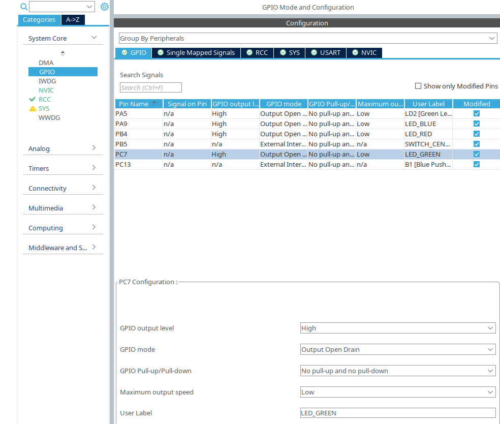
Due LED connecting reasons, set the GPIO settings to:
GPIO ouput level: ‘High’
GPIO mode: ‘Output Open Drain’
Select an informative user label.
GPIO Output Settings
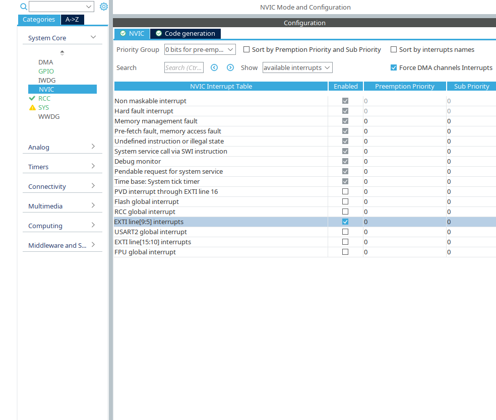
Select the EXTI interrupt for
center switch buttonEnable the EXTI interrupt in the NVIC settings
NVIC Settings
Finish project setup with generating code.
Implementation
The first step for the implementation is to check the interrupts and the led output.
Interrupt setup
Define in your project the function
HAL_GPIO_EXTI_IRQHandler().Check that the interrupt is fired from the
center switch buttonand detect the rising or falling edge.Enable in the rising edge the
blue LEDand disable it in the falling edge.
After the interrupt works with the led control, the next goal is to measure the pressed time with the Systick handler.
The interrupt function SysTick_Handler(void) is called per default every millisecond.
This is the time base of the HAL library.
HAL uses the Systick per default as the clock source to abort blocking functions after a desired time.
The needed functions for this functionality are HAL_IncTick() and HAL_GetTick().
Warning
This two tick functions can be changed by the user, but this is not recommend due to possible undesired side effects in the HAL library. It is better to extend the interrupt by an own defined function to process a task every ms.
To measure the pressed time, use the Systick with a concept of your choice.
Measure pressed time with the Systick
Start measuring at the rising edge of the
center switch button.Stop the measuring and save the value in a variable at the falling edge.
To show the measured time, use the green LED and light it up in the measured time immediately after releasing the measured button.
Light up the LED in the measured time
Enable the
green LEDat the falling edge callback.Disable the
green LEDafter the measured time duration.
To fix an issue when both processes are active at the same time, disable the possibility to measure the button during display process.
Disable measuring during display current time.
Extend your application to not start a new measure during the display process of the current measured time.
Discussion
Discuss with your colleagues the following questions:
What are advantages/ disadvantages of this system?
What is your maximum time to measure?
Is your application robust to over-/underflows of the time variable?