Lab-2.02: Getting Started with CAN-Bus
The Controller Area Network (CAN) protocol was officially released in 1986 with the aim of reducing the length of cabling in a vehicle, thereby reducing cost and weight. In 1991, this goal was achieved and the first car with this serial communication bus went into production. Since then, the CAN bus has been standardised in two versions, high-speed CAN and low-speed/fault tolerant CAN. This leads to a lot of applications where CAN bus is used in our world such as vehicles, industrial automation, lifts, medical instruments and many more. This exercise is about implementing two UART-CAN gateways (implemented with the MCU board and the CAN adapter). Messages will be sent to the gateway using UART and transmitted from the gateway to the remote device via CAN. Data is exchanged between the devices using high-speed CAN.
Objectives
UART communication
CAN bus initialization, configuration and implementation
Design of a UART-CAN bi-directional gateway using the STM32 MCU
Outcomes
Understanding the use of CAN filters
Understand the CAN address system
Understanding the difference between high-speed and low-speed CAN bus
Benefits of a stuff bit
Using CAN to send and receive messages
Using the STM32 as a gateway device between CAN and UART
Using UART to communicate with CAN
Description
CAN bus history
Development of the Controller Area Network (CAN) began at Robert Bosch GmbH in 1983. The protocol was officially released in 1986 at the Society of Automotive Engineers (SAE) conference in Detroit, Michigan. The first CAN controller chips were introduced by Intel in 1987, followed shortly thereafter by Philips. The aim of this serial communication was to reduce the length of wiring in a vehicle, thereby reducing cost and weight. The Mercedes-Benz W140, launched in 1991, was the first production car to use a CAN-based bus system.
CAN bus applications
CAN is used as a communication method in many applications today:
Passenger vehicles, trucks, buses
Agricultural equipment
Electronic equipment for aviation and navigation
Industrial automation and mechanical control
Elevators, escalators
Building automation
Medical instruments and equipment
Model railways
Ships and other maritime applications
Lighting control systems
CAN bus organization
CAN is a digital multi-master asynchronous serial bus. The participants are called nodes. All nodes are connected by a differential bus signal. The bus is a pair of wires with an impedance of .
CAN bus schematic

CAN bus organisation. Source: Wikipedia/CAN_bus
Line terminations are required in a CAN bus system because CAN communication flows are bidirectional. The termination at each end absorbs the CAN signal energy and ensures that it is not reflected from the cable ends. Such reflections would cause interference, resulting in a degradation of the signal quality (reduction of Signal Noise Ratio SNR). The reflection will increase the bit error rate and the demand for low bit rates to ensure error-free transmission. Therefore, proper termination is a challenge in larger CAN networks.
See also
For more information on the terminating resistor, see also here
Physical bus organisation
In 1993, the International Organisation for Standardisation (ISO) published the CAN standard ISO-11898. This specification consists of four parts. The first part, ISO-11898-1, contains the standard protocol. The second part is ISO-11898-2, also known as High-speed CAN, which defines the voltage levels of the signal.
See also
ISO publications of protocol ISO-11898-1 and high-speed ISO-11898-2
High-Speed CAN Signaling

CAN high speed signaling. Source: Wikipedia/CAN_bus
To transmit a logical 1, the two wires have the same voltage of . To transmit a logical 0, however, the voltage levels change. The voltage of the CAN high wire is raised to and the CAN low wire is lowered to . This makes the CAN bus very robust to signal interference. Like the UART, the CAN bus is an asynchronous transfer mode, which does not carry a clock. This means that a baud rate must be agreed at which the data will be transmitted. The maximum speed depends on the length of the cable. Typical values are listed in the bitrate to distance table.
Table bitrate vs. distance
bitrate / kbit/s |
|||||||
distance |
For optimal results, the CAN bus termination should match the nominal impedance of the cables, which for this standard is specified as . Therefore termination adapters are considered the standard for CAN bus. Today there is another variant of the CAN bus, the ISO-11898-3, also called low-speed or fault-tolerant CAN.
See also
ISO publication of low speed CAN ISO-11898-3
Low-Speed CAN Signaling

CAN high speed signaling. Source: Wikipedia/CAN_bus
CAN bus signalling works in a similar way to the ISO standards mentioned above. The differences are in the voltage levels of the dominant and recessive states, as shown in Figure Low-Speed CAN Signaling. The advantage of this configuration is a higher voltage difference between the two lines and the logic voltage states. The recessive state between CAN-Low and CAN-High produces a negative voltage, while the dominant state produces a positive voltage. This makes the signalling more reliable and resistant to noise, but slower. The bit rate of these systems is limited from to only . Another difference is the termination resistor; low-speed CAN uses resistors at each node. The total termination resistor should be close to, but not less than .
See also
For more information on CAN, see the can-bus-grundlagen page.
CAN protocol
Both voltage level configurations use the same protocol for data transfer. Do an internet search and answer the following questions about the frame format:
Question
How many frame sizes are standardised?
What is a stuff bit and why is it used?
How many bytes of data can be sent in a data frame?
Solution
Two frame formats are standardised for the CAN bus. They differ in the identifier size:
Basic frame format with 11 identifier bits
Extended frame format with 29 identifier bits
See also
To ensure sufficient transitions to maintain synchronisation, a bit of opposite polarity is inserted after five consecutive bits of the same polarity. Example: 11111 0 or 00000 1
See also
8 bytes can be sent in one frame.
D-Sub plug
Although CAN would use only two wires plus generally a power and ground wire, it is common to use the D-Sub 9 connector. Find the answer to the following questions about the pinout of a D-Sub 9 connector with CAN bus:
Question
To which pins are the CAN-H and CAN-L signals connected?
What are the other pins connected to?
Solution
CAN_L on pin 2 and CAN_H on pin 7
As shown in the diagram below, reserved for power supply or other user-defined wires.
CAN DSUB 9-pin connector
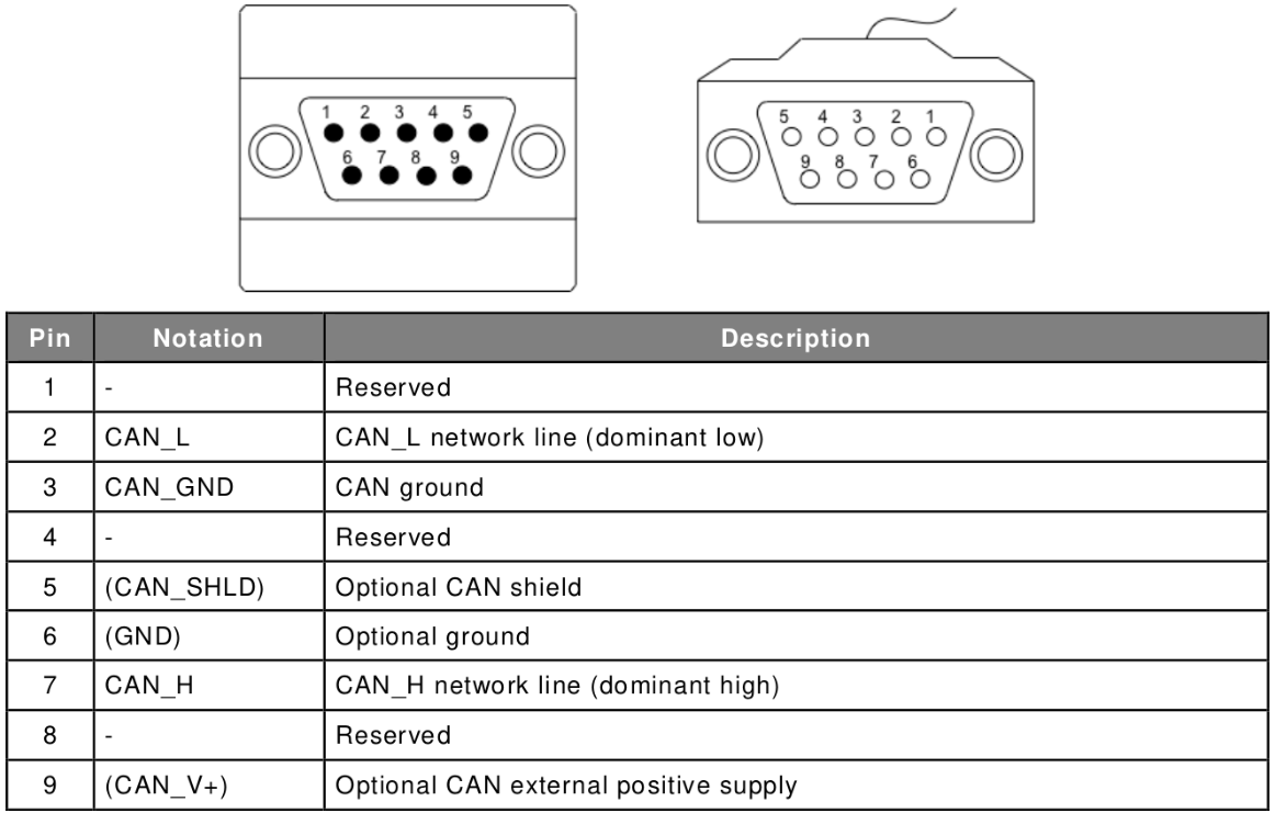
CAN DSUB 9-pin connector pin-out
Tasks
You will design and implement a high speed CAN bus UART adapter using the nucleo-F446RE and the CAN bus adapter from the BFH. The aim is to send data via the UART from the computer to the controller. The controller then parses the received message. After parsing, the message is sent over the CAN bus to the desired destination (target device). Finally, the receiving node transmits the message via UART to the computer.
Labor Test Bench Setup

Setting up the work bench
To achieve the goal, you need to work in tandem. One member of the team is User 1 and the other is User 2, as shown in the figure work bench setup.
UART communication
Before working through the CAN tasks, we start with the UART for communication between your microcontroller and the computer. This is used to handle CAN messages and CAN settings, and the appropriate commands must be defined. For our application at least the following methods are required.
Command |
Arguments |
Description |
|---|---|---|
getAddress |
None |
Get the current CAN address (filter value) of your gateway device |
setAddress |
address |
Set the CAN address (filter) of your gateway device |
sendMessage |
target address, message |
Send a CAN message with the specified message ID (address) |
CAN configuration
Before the lab exercises can be carried out, questions about various CAN bus settings need to be answered. The aim is to configure the CAN bus to operate in high-speed mode with a speed of . To use CAN with the MCU, an adapter is required to set the correct voltage levels. Use the Nucleo-64 schematic and STM32 Nucleo CAN Adapter schematic to find the used GPIO pins and CAN peripheral.
Question
To which GPIO pins are CAN_H and CAN_L connected?
Which CAN peripheral is used for these pins?
Solution
CAN_TX on PA12 and CAN_RX on PA11
The CAN IP CAN1 is used
The CAN peripheral can be configured by reading the sample point of a bit. Read in the reference manual RM0390 on page 1063 how to get the nominal bit time and how to derive the desired baud rate from . The same figure describes how the nominal bit time is divided. There are three segments involved. The SYNC_SEC is the synchronisation segment and defines the duration of a time quantum. Bit segments 1 and 2 (BS1 and BS2) are used to define the sampling time. At this time, the CAN bus circuit checks the input voltage values. Their perfect position can be studied in more detail in the scientific publication referenced below. Special attention is given to the CAN bus consistency check:
The tested baud rate sampling point adapts to the range of 60%-80%, and the characteristic value is 70%.
With this information, the register values can be set to the correct values to achieve the bit rate of .
See also
The publication can be found at Research on CAN bus consistency test method. You can also find more information about signal edge time, signal delay and bus utilisation.
Question
What is the formula for the sample point?
What is the nominalBitTime for ?
How would you set BS1 and BS2 for a time quantum of 100ns?
Solution
Calculation path
From exercise description:
With defined 70% as sample point:
Implementation
Project initialisation
Before using CAN in this exercise, check that the project compilation and UART communication are working as expected. Start a new standard project or use a previous exercise as a template.
Project setup and UART communication
Create a new STM32CubeMX project with default configuration.
Add a method to receive a message with UART without polling. You can echo the received message back to the host as a test.
Parse the received message with your communication concept. Your concept should at least understand the commands discussed above.
Test your commands using the debugger.
CAN bus
The CAN configuration is not as easy to configure as the UART. It has more properties that you will need to parameterise. The aim is to configure the CAN bus to operate in high-speed mode at a speed of .
CAN-Bus initialisation in STM32CubeMX
Enable the correct peripheral and GPIO pins as discussed in the tasks section.
Set the prescaler and the two TimeSeg1 and TimeSeg2 (time quanta bit segment 1 and 2 in the STM32 CubeMX application or the initialisation object) to set the sample point to 70% and a bitrate of .
Set the operating mode to
Normaland ReSynchronization Jump With to 1.Tip
To test your CAN bus configuration without a colleague, change the operating mode to
Loopback. This combines receiving with sending and your application can read the CAN message sent. Other devices can also read your message, but your device can no longer receive messages from other devices!Deactivate all other parameters.
To receive messages, the interrupt on the buffer FIFO 0 will be used. Enable for this the interrupt on
CAN1 RX0.Generate code and close STM32CubeMX.
After initialisation, the CAN bus cannot yet receive or send messages. To receive a message, CAN uses a filter to check if the message is addressed to the device.
Setup CAN-Bus filter
Create a new module with header and source files for CAN bus handling.
Read the doxygen documentation from the
CAN_FilterTypeDef.Create a new function prototype to set a CAN bus filter. Take the CAN_HandleTypeDef, the gateway address and the filter bank (can be a constant) as arguments.
setFilter function prototype
HAL_StatusTypeDef canbus_setFilter(
   CAN_HandleTypeDef *hcan,
   uint32_t gatewayAddress,
   uint32_t filterBank);
Implement the new function:
Create a new
CAN_FilterTypeDefinstance for configuration.Configure the filter instance.
Configure it according to the following guideline:
FilterIdHigh
Set the desired CAN node gateway address. As this is an 11-bit value, shift the address so that the MSB is at position 15.
FilterIdLow
Set to zero as it is not used yet.
FilterMaskIdHigh
Set to
0xFFFFto enable the mask on each bit, resulting in a “must match”. See RM0390 on page 1056 for more information.FilterMaskIdLow
Set to the same value as FilterIdLow.
FilterFIFOAssignment
Expected to be
CAN_FILTER_FIFO0orCAN_FILTER_FIFO1. Use FIFO0 as the interrupt is used for this buffer.FilterBank
Use an argument value or constant for a number between the possible ranges described in the Doxygen documentation.
FilterMode
Since we only want to set one address, use
CAN_FILTERMODE_IDMASKand notCAN_FILTERMODE_IDLIST.FilterScale
Use the
CAN_FILTERSCALE_32BITscale.FilterActivation
Enable the CAN filter with the
CAN_FILTER_ENABLEflag.SlaveStartFilterBank
We use a single CAN instance. Read the doxygen comment for SlaveStartFilterBank for more information.
Register the filter with the CAN instance by calling the function
HAL_CAN_ConfigFilter().
By activating the previously configured filter, the CAN bus is able to receive messages for the configured address. As we have activated the interrupt mode on RX0, you can use the callback function of HAL. The zero of RX0 refers to the first FIFO buffer (index 0 FIFO0). The callback function has the following prototype: void HAL_CAN_RxFifo0MsgPendingCallback(CAN_HandleTypeDef *hcan).
CAN RX FIFO0 Callback implementation
Write the function definition for the
HAL_CAN_RxFifo0MsgPendingCallback().Study the function
HAL_CAN_GetRxMessage()including the argumentCAN_RxHeaderTypeDef().Implement a handler to receive messages from CAN. Remember on how to use UART with receiving messages.
Use the above function to get the data received from the CAN bus.
Hint
Before calling the function, create an instance of the
CAN_RxHeaderTypeDef()structure and pass it as a reference.Store the current length in your receive message handler. The length is stored in the RXHeader structure in the DLC member.
To send a message, HAL provides a similar interface and methods to those described above for receiving.
The aim is to implement a function in the CAN bus module to send any message.
The function is needed to configure the CAN_TxHeaderTypeDef() correctly.
Implement a CAN transmit function
Add a new function declaration to your CAN bus module:
Question
What do you need as arguments for this function?
Solution
This function requires at least the following arguments:
CAN_HandleTypeDef* hcan, reference to the CAN handler instancechar* data, the message to send, can also be auint8_tuint32_t targetAddress, the address of the target device
Create an instance of a
CAN_TxHeaderTypeDef()structure.Unlike the receive function, you must assign the values to the structure for the send function to work. Follow the instructions below:
StdId
Set the address of your destination.
ExtId
The extended form of the address. This is unused as we will use the standard form from above.
IDE
Set
CAN_ID_STDorCAN_ID_EXT. We use the standard (STD) form with 11 identifier bits.RTR
Set
CAN_RTR_DATAto send a data frame.DLC
Set the number of data bytes to send. See the possible range in the Doxygen documentation from DLC.
TransmitGlobalTime
Disable transmission of the global time to be sent with byte 6 and byte 7.
Create the possibility to send messages.
Finally call the HAL function
HAL_CAN_AddTxMessage()to transmit the data bytes. Pass an emptyuint32_tvariable as the mailbox argument.
When everything is ready for testing, set up a test implementation to send and receive some messages from your colleague.
Test CAN communication
Transmit the received CAN messages to your computer via UART.
Set a fixed CAN address for your gateway. Make sure that your colleague does not have the same address as you.
Start the CAN peripheral with the function
HAL_CAN_Start().Activate the CAN bus receive interrupt using the
HAL_CAN_ActivateNotification()function. Enable it for the receive FIFO0 interrupt. You can use the macroCAN_IT_RX_FIFO0_MSG_PENDING. Put it in your main function.Use CAN to send a constant message to your colleague every second.
Connect two boards with a cable and send some test messages.
Hint
Do not forget to connect the terminating resistors.
CAN gateway
Now that you know that the UART and CAN bus work, connect the two peripherals together. Implement the gateway using the code you have written. You can use most of the code directly, only small adjustments are required.
Implementation of CAN gateway
Process the
setAddresscommand with yoursetFilter()method.Return the current address of your filterBank (given as an argument or constant in your
setFilter()method) withgetAddress.Hint
One solution to this problem is to access the filter bank register directly and return the current stored address. The register would be the Filter bank i register found in the RM0390 on page 1085. You can access the filter bank using the CMSIS library. CAN has a member
sFilterRegisterwhere you can access the filter bank and the corresponding stored address.Extend your CAN send function to send data longer than a CAN data frame.
Use the
sendMessagecommand to transmit the message to the defined destination address from the arguments via CAN.Test your implementation with your colleague.