Ex-20: Getting Started with HAL and CubeMX
Configuring peripherals at the register level results in very efficient behaviour, but as you may have experienced, it is also error-prone and requires a high level of target-specific knowledge. To overcome this, a well tested (but not error-free) library such as the ST HAL (Hardware Abstraction Layer) can help. In addition to the library, ST provides a graphical tool called STM32CubeMX for straightforward configuration of STM32 microcontrollers. This tool is available for the three most popular operating systems. Although ST also provides an IDE for developing C code, we will use the VS Code. This exercise aims to install the tools used, to get a first experience with the new applications and to implement a flashing LED application with HAL.
Objectives
Getting Started with CubeMX
Extend your VS Code installation with specific extensions
Create a STM32 Makefile project with CubeMX
Build run and debug with VS-Code
Implement a blinking LED with the HAL library
Outcomes
Using the Application CubeMX
Using a STM32 Makefile project with VS-Code
Initialise GPIO Pins with CubeMX
Implementing a flashing LED with the HAL library
Description
CubeMX is a graphical tool that helps you to configure your MCU. In this application, all the peripherals with their possible initialisations and the clock configuration can be set to the desired values. Finally, an overall project with the initialised peripherals used is generated. This configuration can of course be modified and expanded as the project progresses.
HAL is a higher level abstraction of the well-known CMSIS library. It is designed to improve developer productivity by reducing development effort, time and cost. The HAL driver layer provides a simple, generic, multi-instance set of application programming interfaces (APIs) to interact with the upper layer.
Abstraction Overview

Abstraction Overview
In a project created from CubeMX, the HAL library will be included in the main.h header file.
See also
The complete HAL library is described in the hal manual UM1725. A generated doxygen documentation is linked at HAL Doxygen Documentation. A description about this documentation can be found at HAL Documentation FAQ.
With these new tools, a simple flashing LED application is the goal of this exercise. Use the LED on the mbed application shield schematic. Follow these instructions for correct installation and configuration of the CubeMX.
Tasks
Installation CubeMX
Installing CubeMX
Download the CubeMX installer from moodle or the official website for your preferred operating system. (Recommended for VM)
Installation from official website
Download the CubeMX application from the official website STM32 CubeMX Download. You will need an ST account to download. You can use your student email for verification.
Unzip the file and run the installer. See the Saleae Download and installation page for Linux users on how to install. (It shows the procedure for installing the saleae application.)
Install MCU and Embedded Software Package(s)
Install MCU and Embedded Software Package(s)
Download the package en.stm32cubef4-vX-Y-Z.zip from moodle or from the official website
Open STM32CubeMX
Install the downloaded package(s)
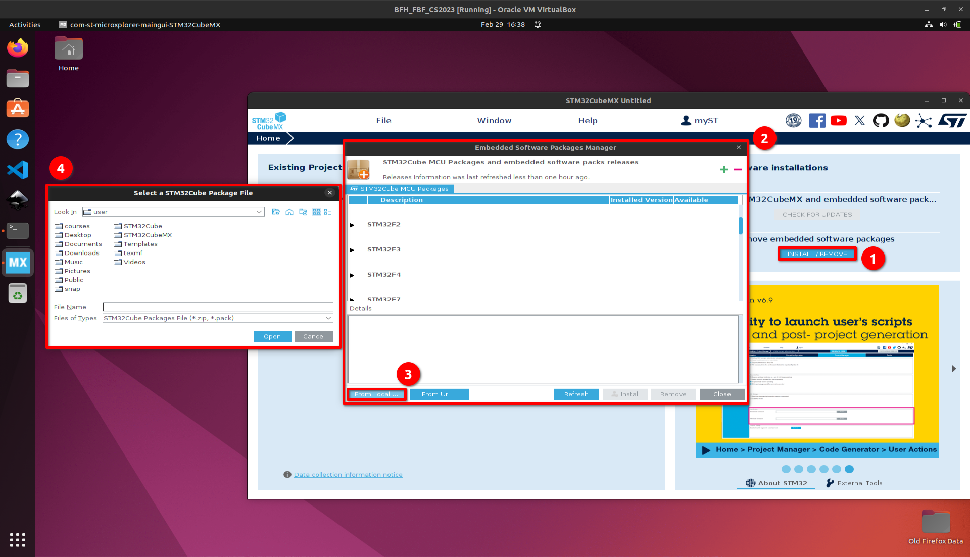
Install embedded software package(s) in CubeMX
Press the install/remove embedded software package button
A new window opens
Use the button From Local…
In the newly opened window, select the downloaded package and press open
Create first project
Once installed, a new project can be initialised with the new software.
CubeMX startup process
Open STM32CubeMX
Create a new project with ACCESS TO BOARD SELECTOR
Startup window
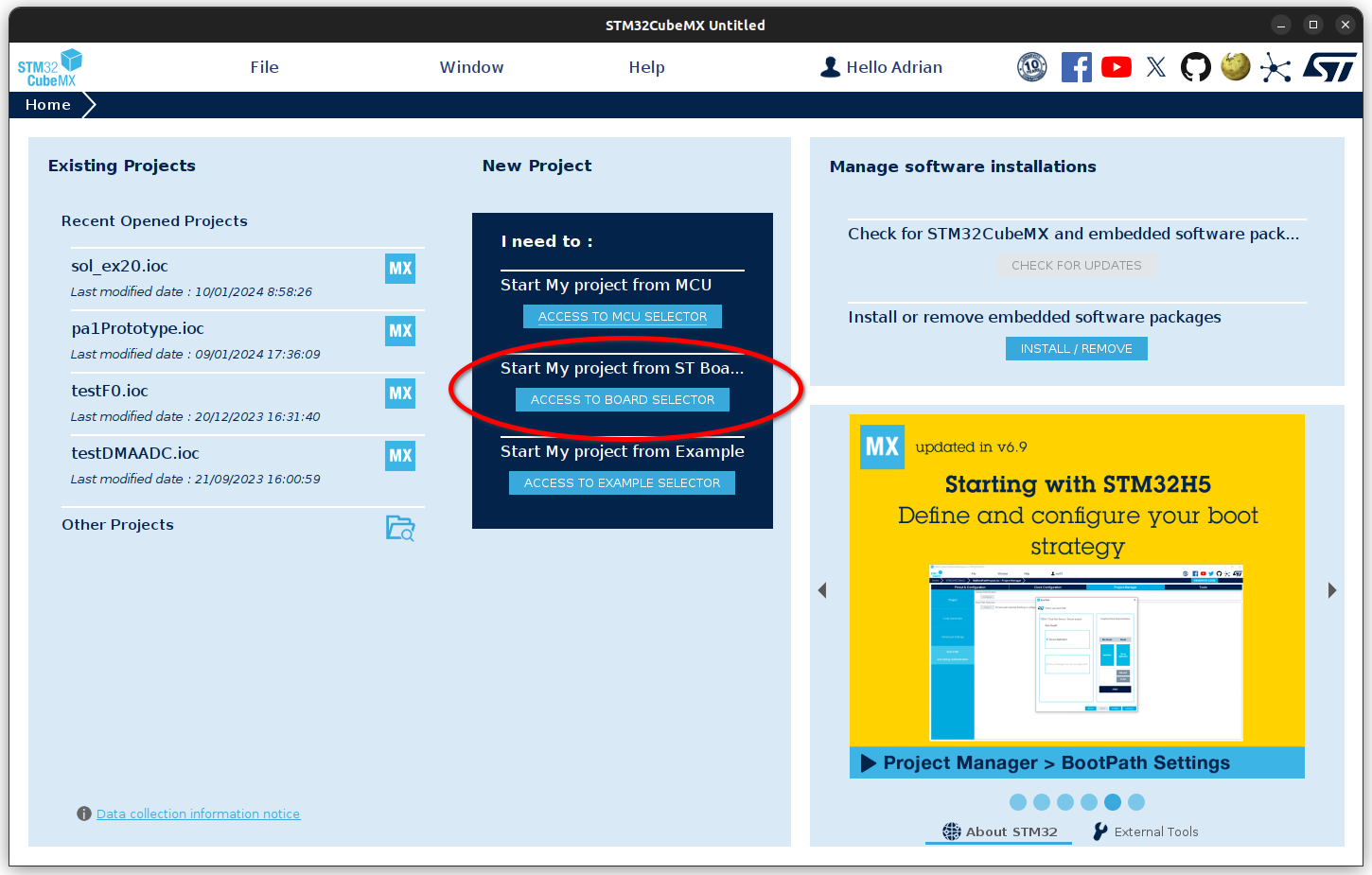
cubeMX startup window: select BOARD SELECTOR
In the new window that opens, select the NUCLEO-F446re board.
Quick Start Guide: Selecting the correct board.
Check that you are in the Board Selector.
Locate the NUCLEO-F446re board.
Optionally, you can select the board as a favourite to find it more quickly in a next project.
Select the board by clicking in the table.
Open the project or double click in the field 4.
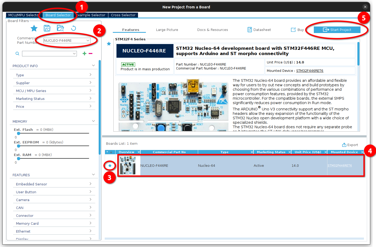
Quick guide to selecting the nucleo-f446re board.
Initialise the board with all peripherals in their default mode.
If necessary, download all the firmware packages for our MCU in the new window. If it is not necessary, the new window should be the Pinout & Configuration. With the default configuration, some pins are already initialised with their occupancy, such as the green LD2 or the user button B1.
Pinout & Configuration window

Pinout & Configuration window with the default initialised GPIO pins.
The next step after the setup process is to manage the project in CubeMX. After these steps, the project is fully initialised and ready to use in VS Code.
Project Management in CubeMX
Set the following settings in the Project Manager menu:
Jump into the Project Manager menu entree
Chose the Project settings
Set the name of the project
Warning
CubeMX will create a new directory with the project name. If you have the project in an existing directory (like an existing git project), set the project name to the same as the existing directory and the project location to the location of the directory. You can check the path in the Toolchain Folder Location field.
Choose the location of your project
Set the Makefile for the toolchain to use the project in VS-Code
All other settings can be left at the default settings
Project menu
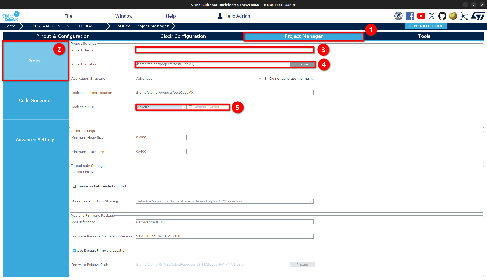
Project manager settings
Enable (2) the setting Generate peripheral initialisation as a pair of ‘.c/.h’ files per peripheral on the Code Generator page (1). This will not write all peripheral initialization to the main.c file, giving you a better overview of the project.
Code Generator menu
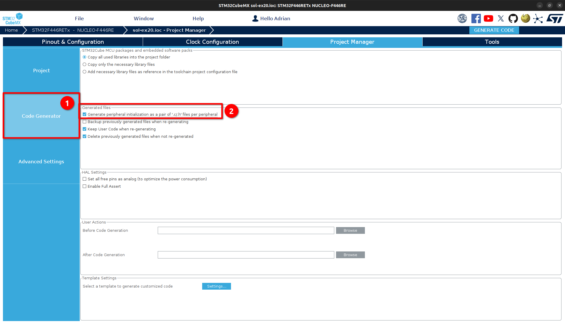
Setting peripheral initialisations as a pair of source and header files
Open the advanced settings (1) and check that the peripherals you are using has the HAL library as a driver selected.
Advanced Settings menu
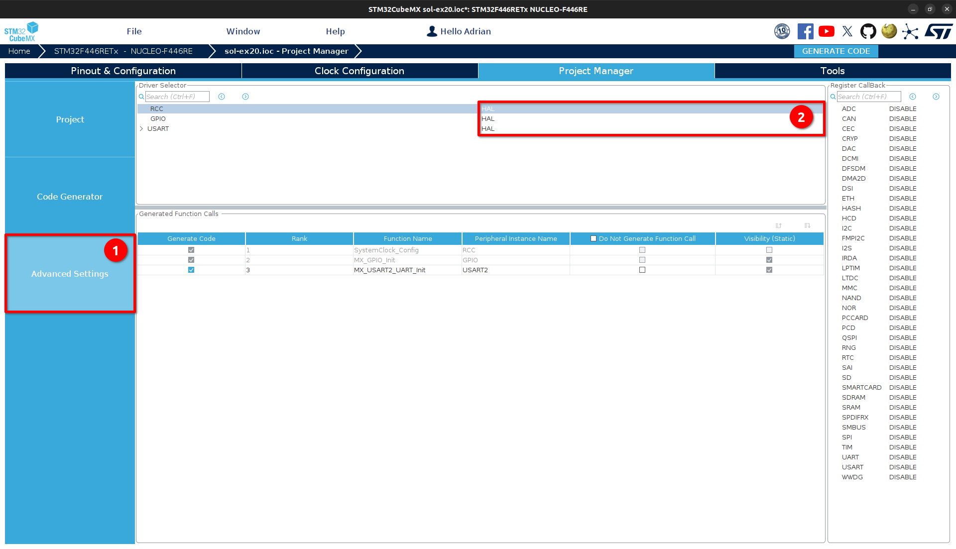
Setting the HAL library as driver for the peripherals
Project initialisation is now complete and the project can be set up. To do this, use the GENERATE CODE button at the top right corner. After each change in CubeMX, save the project and generate the code to get the new state in VS Code.
Generate Code from CubeMX
Generate the code in cubeMX
GENERATE CODE Button
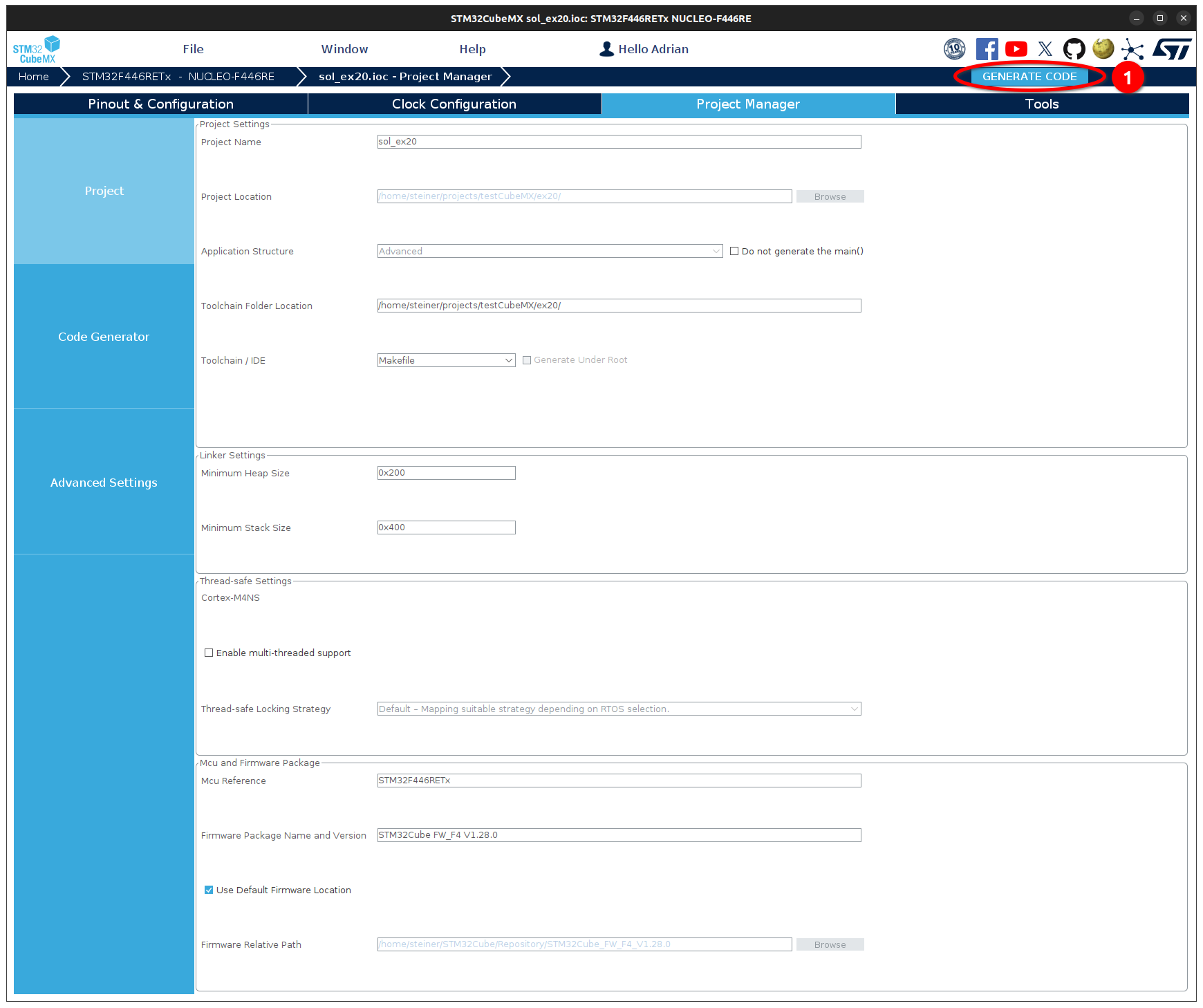
Generate Code Button (1)
Setup and debug in VS Code
In VS-Code, two extensions are required to compile, flash and debug an ST project. The stm32-for-vscode extension is used for compiling and flashing, and the Cortex-Debug extension is used for debugging.
Installing VS Code extensions
Open VS-Code and open the explorer with Ctrl+P
Install extension stm32-for-vscode
ext install bmd.stm32-for-vscodeInstall extension Cortex-Debug in VS-Code
ext install marus25.cortex-debugFor more comfortable c-programming, we recommend installing the extension C/C++
ext install ms-vscode.cpptools
After the installation of the additional extensions, VS Code is ready for use and a first build, flash and debug session can be started.
Error
If you get an error during the exercise below, see the FAQ entry STM32 for VS-Code for more information and help.
Build, flash and debug project
Open project folder in VS-Code
Note
Open the root directory of your project. This is important to detect the cubeMX makefile project.
VS-Code Startup Window
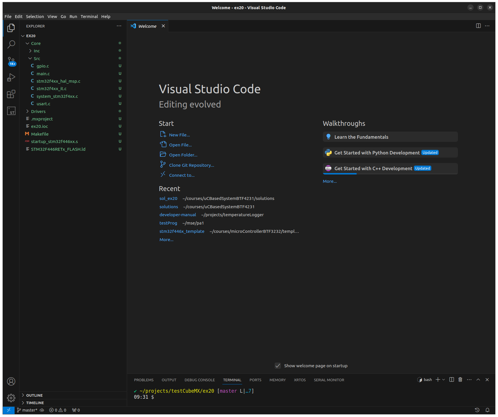
VS Code Startup Window
Build project
Build the project using the Build button in the Extensions menu.
Attention
If no new extension appears on the left, you have not opened the correct directory or the extension is not installed.
VS-Code Build
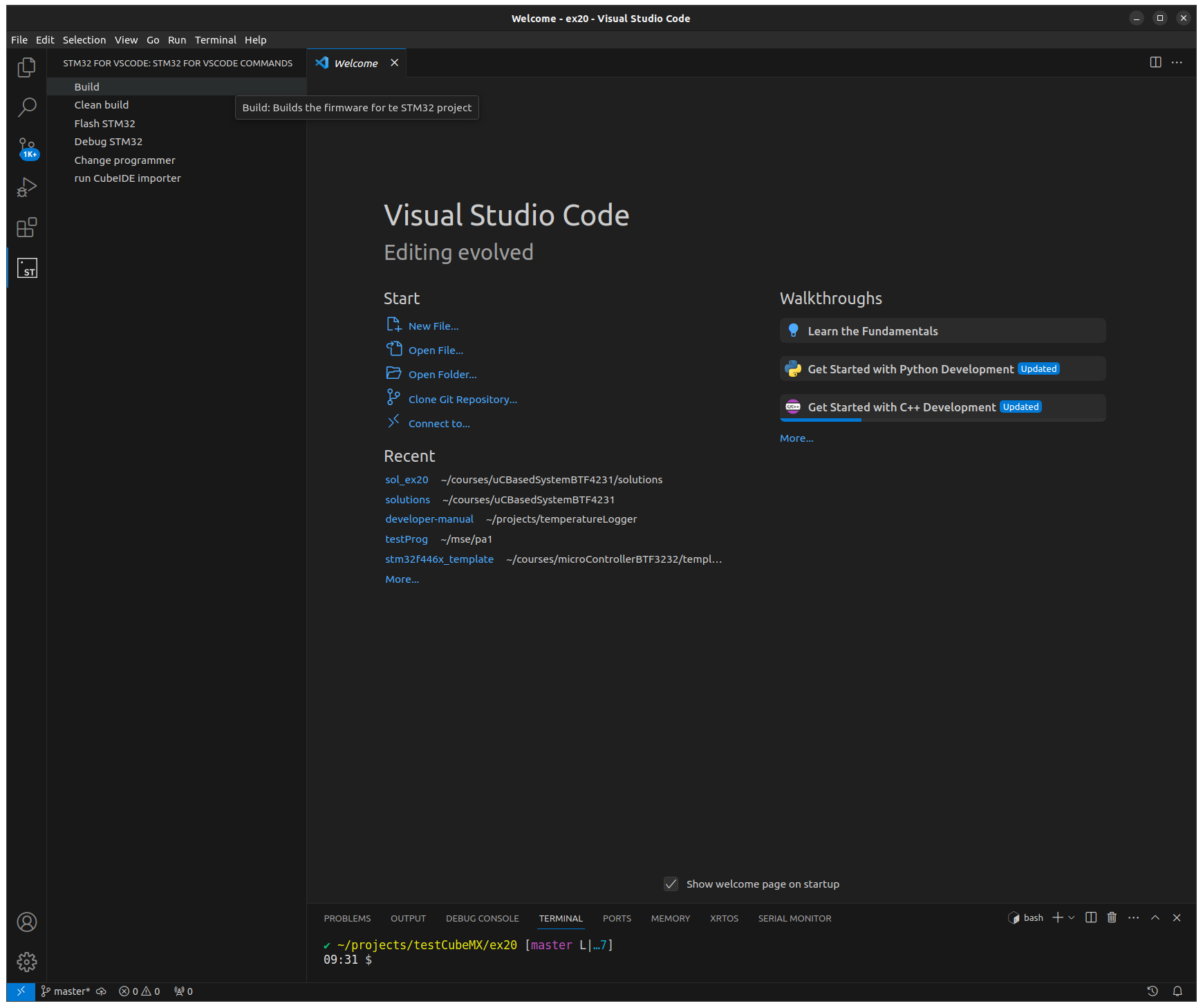
VS Code Extension view
Check new generated files
The extension adds new files to the project to generate code on all major operating systems. Check that the following files are added to your project:
openocd.cfg
STM32-for-VSCode.config.yaml
STM32F446.svd
STM32Make.Make
Missing STM32F446.svd file
Download the SVD file
The System View Description (SVD) file defines the addresses of the peripherals and the functionality of the corresponding registers and bits for debugging. It is supplied with the CMSIS package. You can download it from the CMSIS package page CMSIS STM32F446 package and extract the SVD file for your MCU or download it here:
STM32F446.svdMove the SVD file into the root directory of your project.
Add the SVD file into your configuration.
The launch.json file in the .vscode directory must reference the SVD file. Add the svd file path attribute to both configuration entries:
"svdFile": "STM32F446.svd"Note
Remember to add a comma at the end on the previous line since it is a comma separated list.
Missing openocd.cfg file
The openocd.cfg is the configuration file to debug the MCU.
Add openocd.cfg file
Create the file openocd.cfg in the root directory of your project. Copy the following content into this file.
## OpenOCD configuration file, generated by STM32 for VSCode

## Programmer, can be changed to several interfaces
## Standard will be the stlink interface as this is the standard for STM32 dev boards
source [find interface/stlink.cfg]

## The target MCU. This should match your board
source [find target/stm32f4x.cfg]
Add to configuration
Add the file path to the launch configuration in the
.vscode/launch.jsonfile."configFiles": [ "openocd.cfg" ]Note
As this is a comma-separated list, remember to put a comma at the end of the previous line.
Debug default implementation.
Use the basic methods to debug an application in VS Code. The functionality is the same as you have used with the template.
VS Code Debugger Window
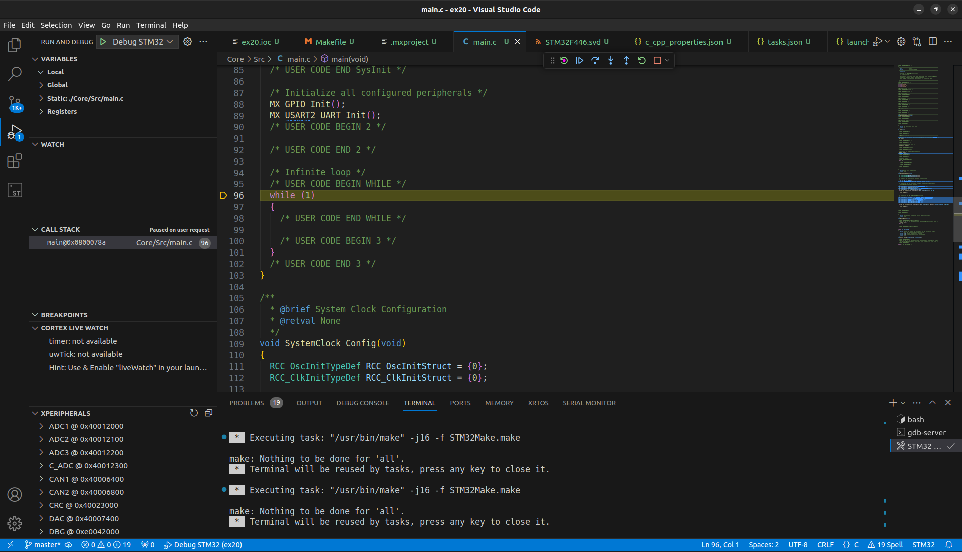
VS Code Debugger window
Hint
Remember on the debug section in the Ex-00 how to start the debugger.
Generate example code
The main.c file is generated by CubeMX and is overwritten each time you use the GENERATE CODE button in CubeMX. CubeMX has developed a mechanism to not change your implementation. Each file has some user sections marked with comments. It does not overwrite the code within these sections.
Start:
/* USER CODE BEGIN <NAME> */YOUR CODE HERE
End:
/* USER CODE END <NAME> */
Example Comment Sections
/* USER CODE BEGIN 2 */
uint32_t myExample = 17;
/* USER CODE END 2 */
Warning
All other implementations not between these comments are deleted in the next GENERATE CODE cycle!
Implementation
The task is to implement a simple flashing LED using the HAL library. Use the LED on the mbed application label.
CubeMX configuration
Open the project in CubeMX again. The ST CubeMX project file is the <projectname>.ioc.
Open the view Pinout & Configuration.
Configure all LED color channels as GPIO_Output.
Left-click to select the desired GPIO pins.
Select the required functionality, in this case GPIO_Output.
Right click on the GPIO pin you want to use.
Select Enter User Label.
Enter a name for the GPIO pin such as
RGBLED_GREEN.
Selection GPIO mode
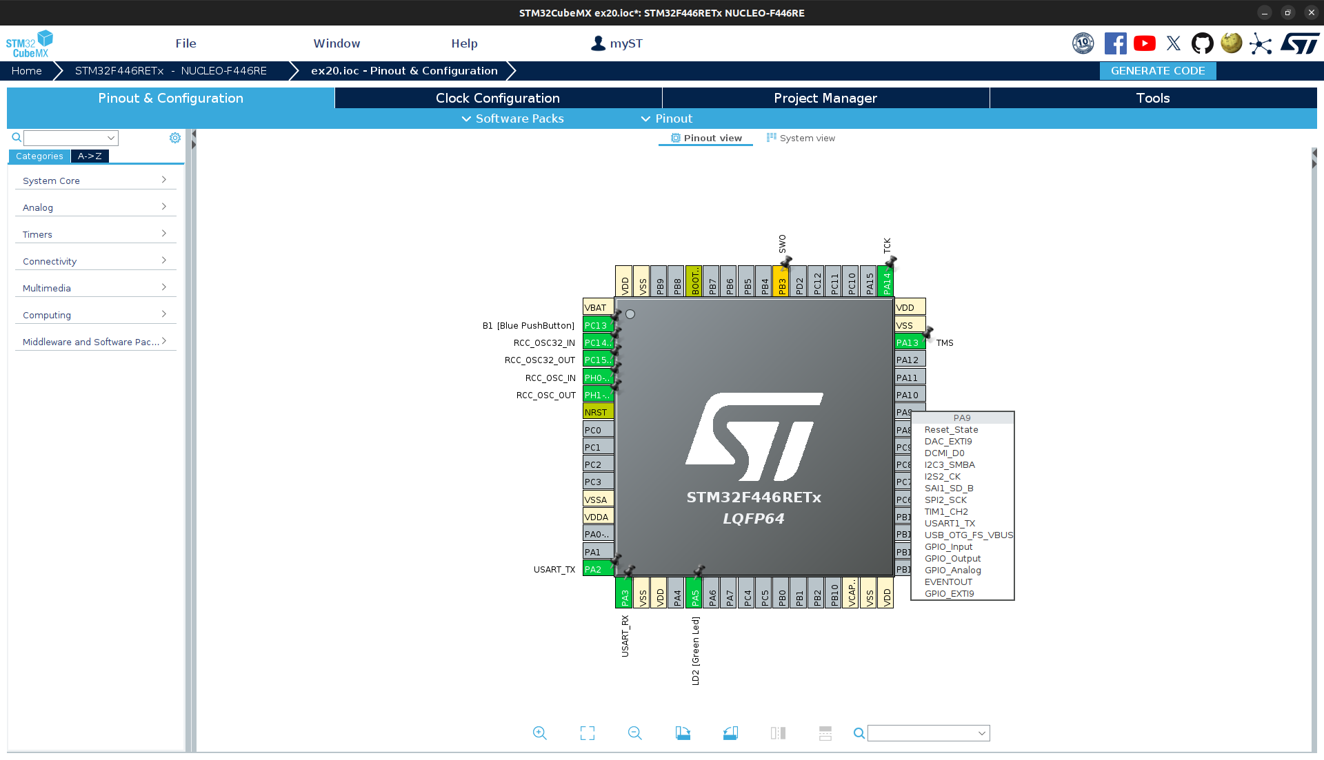
CubeMX GPIO configuration
Change clock configuration.
The clock configuration can be changed by setting the source and the pre- and up scaler values. Change the source to:
PLL source to HSE
System Clock source to PLLCLK
The clock speeds listed below are used by the system:
SYSCLK: 64MHz
APB1 peripheral clocks 32MHz
APB1 timer clocks 64MHz
APB2 peripheral clocks 64MHz
APB2 timer clocks 64MHz
All maximum values may not be exceeded
Note
This is just an exercise and will not be used in every project. The default configuration would also work in this case.
Save the configuration and generate the code.
After the project setup, implement the logic to toggle a LED.
VS Code implementation
A HAL function can be used to toggle the GPIO state and thus realise a flashing LED using the superloop approach.
Tip
Initialisation is done by CubeMX. You can use the HAL functions directly. Have a look at the HAL functions:
Use the blocking HAL function
HAL_Delay()to make the LED flash.Test your implementation.
(optional) Use own main function
Since the main function is error-prone and unreadable with the concept of comment sections, create your own main function in your own main file to isolate your code from the generated code. This leads to better readability, reliability and reusability.
Create a header and source file for your new main function.
Create a custom main function (Name it
<PROJECT>_main()or use any other name that makes sense in a real-world context.).Include your header file in main.c and call your main function in the superloop.
Implement your main function including the initialisation and your own superloop.