Ex-25: Inter-Integrated Circuit (I²C) Logger
In this exercise you will implement a temperature logger based on the LM75 Digital Temperature Sensor. The sensor data is read out via the I²C bus. The logger can be controlled by your computer via UART.
Objectives
Read a sensor with I²C
Convert two’s complement value to MCU readable temperature
Use a cyclic readout procedure
Implement a communication system between your MCU and a computer
Use control commands to control the behaviour of the firmware
Outcomes
Learn how to use I²C to read data from a sensor
Convert data into a firmware compatible format
Create a protocol for message exchange
Process commands from the computer to the MCU
Description
Reading a sensor with an MCU and transmitting the data to a computer is a common task in practice. The MCU collects all the data from the sensors and sends it as a packet to the host. The host can set some parameters in the device. This scenario has to be implemented in this exercise.
UART is used as the communication method between the computer and the MCU. The MCU reads the LM75 Digital Temperature Sensor on the mbed application shield using I²C. When the reading is complete, the result is converted into a format that can be further processed by the MCU. Finally, the converted result is sent to the host.
The user can set the readout frequency and the accuracy of the received data via the host computer. For practical reasons, it is also necessary to be able to return the current settings.
Tasks
There are three steps to be taken to complete this exercise:
I²C configuration
When using I²C in a system, the two most important configurations are the timing behaviour and the address management. The specifications and information can be found in the datasheet.
Question
What is the maximum operation frequency of the LM75 Digital Temperature Sensor?
What I²C speed would you configure?
What size is the address of the IC?
What is the address of the LM75 Digital Temperature Sensor on the mbed shield?
Tip
You need the mbed application shield schematic to answer correctly this question.
Solution
, found in the datasheet LM75 page 22.
Although the high speed mode would be possible, the standard mode of for one sensor is sufficient for this application.
The address has a size of 7 bit as it can found in the datasheet LM75 section 7.3.
The possible configuration of the address can be found in the same section as before. As you can see in the mbed application shield schematic, the three config bits are set to logic 0. This results in an address of 0x48.
What is still missing is which GPIO pins and I²C peripherals are used for the sensor. This can be determined by reading the schematic and checking which alternative function can be enabled on these pins for an I²C peripheral.
Question
To which MCU pins are the bus wires connected?
Which I²C peripheral is used?
Solution
Signal
Pin
SCL
PB8
SDA
PB9
The only possible I2C alternative functions on these pins are for the I2C1 peripheral.
With this information the I²C configuration can be implemented.
I²C configuration
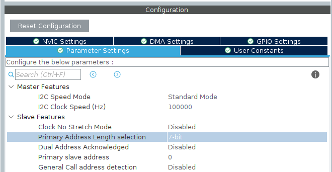
Configuration I2C
Transmission of data at regular intervals
There are several ways to process a task with a specific period. It is desired that your solution does not block the system. You have learnt several methods to solve this problem, choose one of your choice.
In the I²C bus system, our MCU works as a master to read the temperature data. To interact with the registers in the sensor, several methods are needed. The datasheet LM75 starting on page 14 describes these possibilities.
Tip
For our goal of receiving only the current temperature, figure 12 in the data sheet shows the workflow on the bus.
HAL provides an abstraction of these functionalities with the write and read functions. These have been implemented in the I2C input and output operation function group.
The received temperature data is represented as an 11 bit 2’s complement value. This needs to be converted into a format that can be handled by the MCU. Finally, the converted data can be sent to the computer via the UART. It is up to you how to send the message.
UART message protocol
There is no default standard for communicating with the UART bus. This must be designed and implemented by the developer. This will result to optimised communication for his device, but also requires a well-documented and bug-free implementation, which is difficult.
For this exercise, you are free to choose how this communication protocol should look like. The communication only has to meet the following requirements:
The receiving part must not block the system
The following commands and responses are expected
Set readout frequency
Returns the current readout frequency as an acknowledgement, e.g. set to 0.1, 0.5, 1, 2 … Hz.
Set current data accuracy
Returns the current accuracy as a confirmation, e.g. set to 1, 0.5, 0.25 … °C.
Get current settings
Returns current frequency and accuracy.
Return an error message if the message could not be read.
A basic solution is given below for those who need some assistance with this.
Example communication
The commands can be summarised in a table:
Commands |
Message |
Return message |
Description |
|---|---|---|---|
Set frequency |
f:dd.dd\n |
#frequency,dd.dd\n |
dd.dd can be a float or fixed point integer to set 0.1 Hz for example |
Set accuracy |
a:dd.ddd\n |
#accuracy,dd.ddd\n |
Sets the accuracy of the returned temperature with dd.ddd = 1, 0.5 … for example |
Get the current settings |
g\n |
#frequency,dd.dd,accuracy,dd.ddd\n |
Returns the current frequency dd.dd and accuracy dd.ddd |
An example of an error message:
#Error,error message,<received message>
To implement a non-blocking system for receiving messages, the UART interrupt is used.
The message is collected there in a buffer and processed after a '\n'.
To handle the buffer, a new structure for storing messages is needed:
Receive message handler
/**
 * @brief Stores the incoming character from UART.
 *
 */
typedef struct {
    char messageBuffer[128]; ///< message buffer to collect the messages
    bool processMessage;     ///< flag to process the message in the superloop
    uint32_t curPosition;    ///< stores the current position to add the new character
    char rxData;             ///< stores the current received character from UART
} uartRxHandlerType;
In the interrupt handler, the received character stored in the rxData member is checked to verify if it is the terminating '\n' character.
If it is true, the processMessage flag is set and the interrupt is terminated, otherwise the received character is inserted into the messageBuffer at curPosition and curPosition is incremented by one.
The processMessage flag is checked in the superloop.
If the flag is true, the message is checked for a valid command and the desired command is executed accordingly.
The standard library functions from the header file string.h can be used for this.
At the end, curPosition is reset to 0 and processMessage is set to false.
Tip
You can extend the structure with additional members like delimiter or end character to parse the message with these members.
Implementation
Project and I²C configuration
Create a new STM32CubeMX project.
Enable the correct I²C bus and pins.
Set the necessary parameters as described in Task 1.
Frequently read out the sensor
Read the sensor data with I²C and test the received data with Debugging.
Tip
Have a look at the function
HAL_I2C_Master_Receive(). Be careful how you set theDevAddress, the meaning is to move the 7bit long address to bit 8 so that the function can set bit 0 to the r/w bit. This is used from the API to allow 10-bit addressing with the same interface.Implement a method to read the sensor periodically (think of a timer interrupt or SysTick).
Convert the received data into a MCU readable temperature.
Send the converted temperature with the same period.
Step 3: UART message protocol
Add a method to receive a message with UART without polling. As a test, you can echo the received message back to the host.
Parse the received message with your communication concept. Your concept should at least meet the requirements. As always, feel free to extend the commands defined in Task 3.
Return the value set, the current settings or the error message as confirmation, again depending on your concept.
Process and use the received parameter in your implementation.