Ex-00: Getting Started with STM32, VS Code and Saleae
The editor used for writing the code and programming the microcontroller will be Visual Studio Code. This is well suited to the students’ experience as it is the text editor used in other programming classes. Visual Studio Code is not specifically designed to work with C/C++ or with a microcontroller. It is more like a general-purpose text editor with syntax highlighting and a plug-in interface for all sorts of extensions. However, the extensions make it easy to install a toolchain for your target architecture. The aim of this lab exercise is to install and configure all the necessary components required to build, flash, run and debug a simple LED blinking application on the microcontroller.
Objectives
Getting started with the text editor “VS Code”
Extend your “VS Code” installation with specific extensions
Installation of the ARM toolchain for STM32 controllers
Implementation of a minimal “blinking LED” project
Build, run and debug the example project
Outcomes
Install and configure the development tools.
Download a sample program and test it on the development board.
Learn how to use the IDE.
Set up the operating software for the logic analyser.
Description
The Visual Studio Code editor will be used throughout this course to program the microcontroller. Although a complete development environment is available from the microcontroller vendor (STM32CubeIDE), it abstracts many implementation details that are intentionally exposed in this course to improve understanding of the embedded software toolchain. For the vast majority of toolchains, regardless of the target platform, it is possible to use them in an environment of your choice. The simplest example is to use a text editor to edit your files and run the toolchain from the console. You may have already gained some experience of doing this in the introductory course to the C programming language in the first semester of study. As the complexity and size of a toolchain increases, it is recommended that you use a development environment to help you manage the necessary components of your toolchain. This environment is referred to as an Integrated Development Environment (IDE). There are many IDEs available from hardware and software vendors. However, this means that you have to use different IDEs for different projects. To counter this trend, many modern IDEs consist of just a text editor and a package manager for extensions. Toolchains for different target platforms can also be installed as packages. This allows a single IDE to support multiple programming languages and target platforms. For this course and the other basic programming courses, Visual Studio Code is used as the IDE. This is because this IDE is widely used in the industry and is also available on most platforms.
Installation and Initial Setup
For this course, as always, we provide a pre-installed virtual machine with the latest LTS version of Debian GNU/Linux. If you do not already have it installed, follow the instructions in the README file linked on the e-learning platform to boot your copy of the virtual machine.
Hint
Make sure you have a fast internet connection. The download is 3.2GB.
It is not an OEM standard installation, as we have pre-installed some of the most important programs and tools you will use. The editor Visual Studio Code is pre-installed. However, the necessary extensions and packages for creating a microcontroller project are still missing.
Template at a Glance
To save time when setting up a microcontroller project, a template has been created. You can clone or download the MCU template from GitLab. This template provides all necessary files to compile, debug and flash the project for a STM32-F446re controller.
A brief explanation of the most important files and directories:
.vscode
This directory contains settings for VS Code, which are used for building and debugging the project in VS Code.
Drives/CMSIS
The CMSIS directory contains important information about the STM32-F446re MCU and will be explained in more detail later on.
src
This directory contains the basic main.c file and allows you to add your additional source and header files.
Makefile
The Makefile contains basic rules and recipes to compile a C project. It optimises the compilation process and reduces the user effort involved in building.
STM32F446RETx_FLASH.ld
This is the linker script used during the linking stage as part of the compilation process to correctly link the libraries used and generate a single machine code executable.
stm32_startup.c
This is used to implement the startup process to set up the hardware state correctly. It ends by calling the
main()function.
Additional linked files:
STM32F446.svd
The CMSIS System View Description format (CMSIS-SVD) formalises the description of the system contained in Arm Cortex-M processor-based microcontrollers, in particular, the memory mapped registers of peripherals. It is used to expose peripherals in the debugger view, enabling registers to be accessed and modified through descriptive names instead of raw addresses. It is provided within the STM32CubeCLT package.
STM32CubeCLT Package
The virtual machine does not have the base packages for a MCU project installed. All important drivers, cross-compilers and additional tools can be installed using a single application called STM32CubeCLT. It is a toolset for third-party integrated development environment (IDE) providers, allowing the use of STMicroelectronics proprietary tools within their own IDE frameworks. You can install it directly from the STM32CubeCLT webpage or use the provided link to the Nextcloud STM packages.
Important
Install all the additional packages that are listed/described in the “Prerequisites” section of the README file in the template.
Start VS Code
Move into the directory where your cloned or downloaded template is located in the terminal. Open VS Code with the command:
code .
The command code opens VS Code, the argument . references a folder or a file, in this case the current directory. When VS Code is started for the first time, a welcome message is displayed.
Starting VS Code
You can choose your own settings for the display, but this will not be part of this exercise since the defaults work fine.
VS Code Extensions
Add the extensions for VS Code listed in the README below the STM32CubeCLT section. The extensions are briefly explained:
Cortex-Debug
ARM Cortex-M GDB Debugger support for VS Code
C/C++ Extension Pack
Popular extensions for C/C++ development in Visual Studio Code, including syntax highlighting, auto-completion and error and warning descriptions
Note
The C/C++ Extension Pack is used for developing native C/C++ projects and is not specific to this course. However, it may be useful to you in the future. Therefore, we recommend that you install this extension.
Additional Recommended Extensions:
Highlight TODO Extension:
It highlights TODO, FIXME and other annotations within your code. Sometimes you forget to review the TODOs you’ve added while coding before you publish the code to production. This extension highlights the configured keywords.
Doxygen Documentation Generator
It automatically generates Doxygen comment templates for functions, files, and other code elements.
VS Code at a Glance
On the left is a menu bar that gives you access to the most common functions:
Explorer
Keep track of all the files and directories in the folder that is currently open
Search
Search bar to find files, directories, functions or words in files
Source Control
Git source control with a user interface. Of course, you can still use the Terminal.
Run and Debug
You can run and debug your program by observing the current values of variables and registers for as long as the debugger is paused.
Extensions
View installed extensions, search for new extensions and get recommendations for new useful extensions.
Explanation side panels
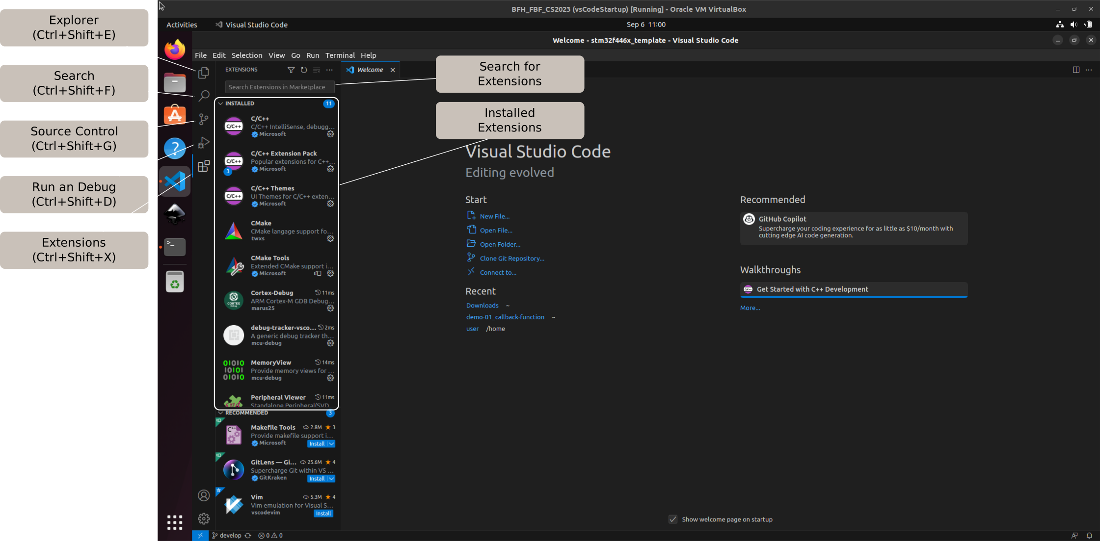
Side panel description
Note
If you add more extensions, there may be more menu items than the default ones.
Compile and Flash
With the help of the Makefile, these processes are automated. There are several possibilities to run these jobs.
Compile
The Makefile automatically invokes the ARM GCC compiler, linker, and additional tools required to generate the executable firmware image.
Compiling
Open the terminal in the directory of your template
Use the command make or make all
Open the terminal in VS Code (you should directly be in the correct directory)
Use the command make or make all
Simply press Ctrl+Shift+B in VS Code, it will execute make all in a new terminal.
Flash
This target first checks whether a valid binary exists and then programs the microcontroller through the onboard ST-Link debugger.
USB Settings
By default, your virtual machine does not have access to the hardware interfaces and devices of your host computer. Therefore, you need to add this permission. You can do this manually for each session or set it once for your virtual machine. To enable a permanent USB connection to your virtual machine, read the USB Settings article in the FAQ section.
USB Settings
In the future, if you want to make other USB devices persistent in your virtual machine, you will need to follow the same procedure.
Run Flash Command
Open a terminal as described in the Compile section and use the command:
make flash
Important
You cannot flash a board if a debug process is running.
Debug
Debug Configuration
The final step is to learn how to debug your program in Visual Studio Code.
By installing the toolchain and extensions and using the template, all the tools are already available and you should be able to examine the ARM-specified “Cortex Registers” at run time.
The configuration file to link these registers with the correct address is the “STM32F446.svd” and is called in the launch file in .vscode/launch.json.
Start Debugger
Ensure that no other debugging session is connected to the target before starting a new debug session. There are several ways to start the debugger.
Start Debugger
Open the Run and Debug on the left side and press the play button at the top.
Click the Run menu at the top
Choose Start Debugging
Press F5
Debugger Menu
This is a brief overview of the sections and panels available in Debugger mode:
Debugger Menus
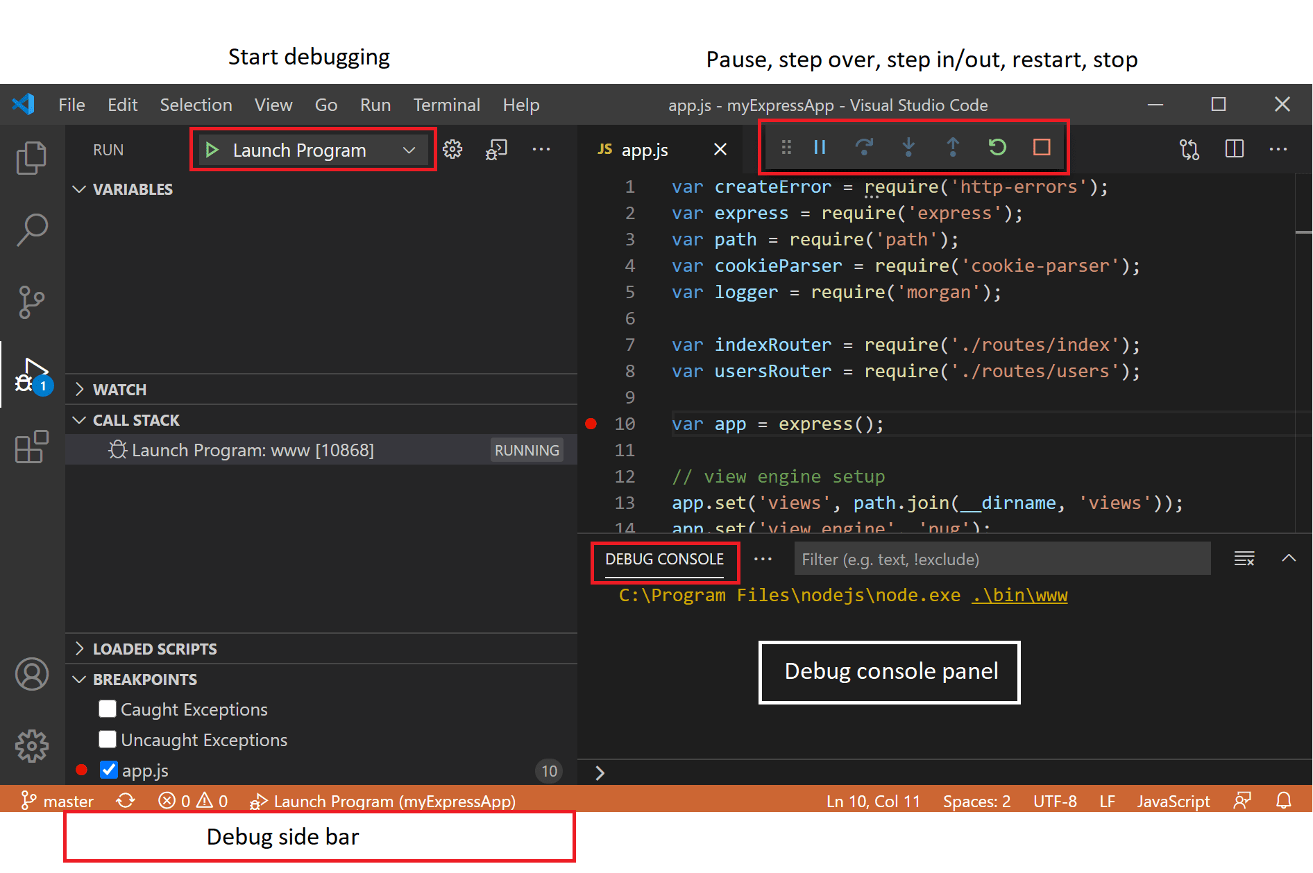
Debugging Menus
Debug Actions
To control the debugging, Visual Studio Code provides a user-friendly control panel. Read the part about the VS-Code Debug Action Buttons.
As a first step, pause the program and have a look at the current state of the program:
On which line are you in the program?
Can you see the current register value of RCC, which belongs to the register named CR (clock control register)?
Example reading MCR Register
Here is a short example of how to read a register value from CAN1, the MCR (Master Control Register) with a decimal value of 65538:
Saleae Logic Analyser
Next, we start with a brief introduction to the saleae logic analyser. This device allows you to read digital inputs, analogue inputs and interpret communication protocols. The aim is to download and install the official Saleae application, connect the logic analyser to your computer, and capture digital and analogue signals.
Download and Install
First, download the Logic 2 application from Saleae Download and installation. Read the Installation Instructions for your operating system. For GNU/Linux users, see the FAQ in the official website section.
Exercise
Objective
The aim is to gain initial experience with the Saleae, including reading an analogue and digital value and making a first measurement. The analogue value is the left potentiometer, called POT_I in the schematic. The digital signal is the switch centre.
Note
This exercise uses only the Nucleo-64 and the mbed application shield, but the thermocouple extension board has no effect on the exercise, you can leave it connected.
Basic information
The first step is to watch the videos linked below:
capturing data to learn the absolute basics
organize workspace for tips and tricks to use the application more effectively
Connect to the Nucleo-64 board
Refer to the schematic of the Thermocouple Expansion Board schematic or the PCB Description for the correct pins for the hardware used and connect PIN 0 of Saleae to the SW_CENTER pin on the Morpho connector. Connect POT_I to PIN 1 of the Saleae.
Tip
In the PCB Description, try using the filter to highlight the pins in the group. In the Pins group there are subgroups for the Switch and the Poti.
At the end, connect a ground wire (Saleae G) to the ground of the Nucleo-64 board.
Important
All grounds on the Saleae are connected together. Be careful not to create a short circuit. Always make hardware changes without power.
Measure the inputs
Start the application and take a first measurement as learned in the capturing data. Read different values and observe the behaviour in the application by pressing the middle button and turning the potentiometer. Answer the following questions:
Question
What is the fastest sampling rate for digital?
What is the fastest sampling rate for analogue?
Do these two systems influence each other?
Hint
Increasing the sampling rate increases the amount of captured data and can reduce the maximum capture duration. Observe how changing one parameter affects the others.